Network Topology
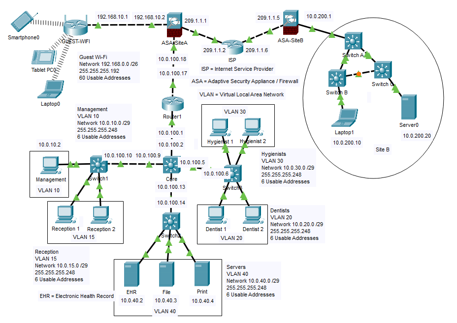
Below is the network topology diagram for my capstone project. It illustrates the segmentation of the network into multiple VLANs, the placement of SVIs, and the overall structure of the network.
Designing Secure and Scalable Networks
Below is the network topology diagram for my capstone project. It illustrates the segmentation of the network into multiple VLANs, the placement of SVIs, and the overall structure of the network.
My capstone project focused on designing and implementing a secure, scalable network infrastructure for a multi-department organization. The goal was to ensure robust security, efficient traffic management, and seamless communication across different network segments.
One of the key aspects of my project was the emphasis on network security. I achieved this by:
SVIs and ACLs were used to enforce security policies at the network edge, ensuring that only authorized traffic could pass between VLANs.
The network was segmented into multiple VLANs to isolate traffic and improve performance. Inter-VLAN routing was configured for necessary communication.
An IPSec VPN was set up between sites to ensure secure communication over the internet, protecting sensitive data from interception.
Tools like syslog and NTP were configured to monitor network activity and ensure accurate time synchronization across devices.
The network was segmented into multiple VLANs to enhance security and reduce congestion. Each VLAN served a specific purpose:
vlan command, and access ports were assigned to the appropriate VLANs using the switchport access vlan command.
ACLs were implemented to enforce security policies and restrict traffic between VLANs. For example:
ip access-list command and applied to interfaces with the ip access-group command.
Inter-VLAN routing was enabled using Switch Virtual Interfaces (SVIs) on Layer 3 switches. Each VLAN had an SVI with a unique IP address, allowing devices in different VLANs to communicate securely. For example:
10.0.10.110.0.15.110.0.20.110.0.30.1ping command, ensuring that only authorized traffic could pass between VLANs.
An IPSec VPN was configured between two Cisco ASA firewalls to secure communication between Site A and Site B. The VPN tunnel used the following settings:
esp-des esp-md5-hmacshow crypto ipsec sa command, and connectivity was tested using ping between devices in Site A and Site B.
Network monitoring was implemented using the following tools and techniques: